Laminate Cantilever Beam Stress Distribution

Pin On Sci O

Tapered Beam Bending Di 2020

Cantilever Beam Shear And Bending Moment Diagrams In 2020 Shear Force Bending Moment In This Moment

Pin Di Beam

I Beam Shear Stress Formula In 2020 Shear Strength Shear Stress Steel Beams

Cantilever Beam Equation Deflection In 2020 Equations Beams Bending Moment
Cantilever beam single load.
Laminate cantilever beam stress distribution. At the fixed end can be expressed as. For this reason the analysis of stresses and deflections in a beam is an important and useful topic. Maximum stress is way below the ultimate tensile strength for most steel. Distribution of sigma xx stresses.
Figure 4 shows the distribution of stresses in the horizontal direction throughout the cantilever beam. Classical laminated theory i e. Accurate stress prediction in composite laminates is crucial for safe design under different loading conditions. It is able to calculate the reactions at supports for cantilever or simple beams.
The maximum stress in the beam can be calculated as. The magnitude of deflection moment and stress depends on the material and the stacking sequence. Many structures can be approximated as a straight beam or as a collection of straight beams. Engineering calculators menu engineering analysis menu.
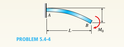
Assuming that the applied moment is m 10 kn x 0 3 m. The cantilever blocking provides lateral stability due to potential high compressive stresses in the bottom flange which cannot be resisted by the nails from the flange to the bearing below. This section covers shear force and bending moment in beams shear and moment diagrams stresses in beams and a table of common beam deflection formulas. σ max 150 mm 3000 n 5000 mm 8 196 10 7 mm 4 27 4 n mm 2 27 4 10 6 n m 2 pa 27 4 mpa.
Figure 3 shows stress distribution in unidirectional and cross ply laminates. Displacements are primarily controlled by the applied load d 11 as a result of q 11 and x for the material specified q 11 0 25 12 10 6 q 11 45 7 617 10 6 and q 11 90 1 507 10 6 the 0 5 laminate is the stiffest and has the least mid surface deflection while the. Those based on the euler bernoulli and kirchhoff hypotheses respectively for beams and plates shells are inaccurate for relatively thick laminates as three dimensional 3d effects such as transverse shear and normal deformations are neglected. Uniyal p misra a 2016 finite element analysis of laminated composite cantilever beam.
Structural beam deflection stress formula and calculator. R a f 2a where. The beam span calculator will easily calculate the reactions at supports. This includes calculating the reactions for a cantilever beam which has a bending moment reaction as well as x y reaction forces.
The follow web pages contain engineering design calculators that will determine the amount of deflection and stress a beam of known cross section geometry will deflect under the specified load and distribution please note that some of these calculators use the section modulus of. And that the beam inertia i 1 12 0 3 m 3. The cantilever blocking also provides a lateral load path from the walls at the end of the cantilever down to the bearing walls below.

The Bending Moment Diagram For Simply Supported Beam Loaded In It Center Is In 2020 Bending Moment In This Moment Beams

Laminated Composite Cantilever Beam With Distributed Load Download Scientific Diagram
Cantilever Beam Divided By Two Element With Distorted Parameter E Download Scientific Diagram

Pin On Beam

A End Loaded Cantilever Beam B Three Point Bending Of A Web Core Download Scientific Diagram

Solved A Cantilever Beam With 0 2 M Thickness Is Fixed At Chegg Com

Max Deflection Of Cantilever Beam With Udl In 2020 Beams Udl Bending Moment

Simplified Analysis Of Negative Shear Lag In Laminated Composite Cantilever Beam Journal Of Aerospace Engineering Vol 33 No 1

Example I Symmetric Tapered Cantilever Beam Download Scientific Diagram

Bending Strength Of Timber Beams In 2020 Timber Beams Beams Timber

Beam Deflection Formulaebeam Type Slope At Free End Deflection At Any Section In Terms Of X Beams Structural Analysis Structural Engineering

Pin On Beam