Laminate Bending Stiffness Matrix

Beam Torsional Stiffness Matrix Di 2020

Bending Stiffness Matrix Elements For Each Laminate Download Table

Steel Beam Deflection Calculator Excel In 2020 Steel Beams Beams Excel

Shear And Moment Diagram Cantilever Beam In 2020 Bending Moment Shear Force Steel Beams

4 1 6 Strength Of Laminates Abbott Aerospace Canada Ltd

Pin On Beam

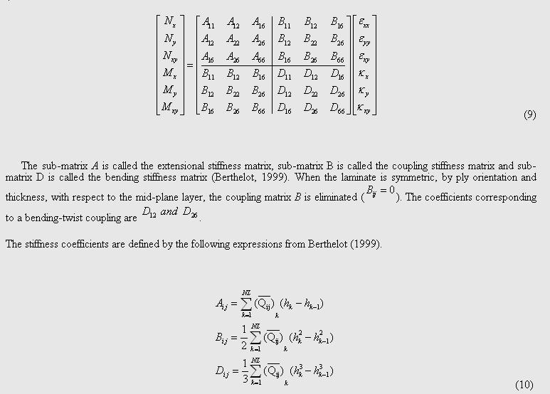
The abd matrix is a 6x6 matrix that serves as a connection between the applied loads and the associated strains in the laminate.
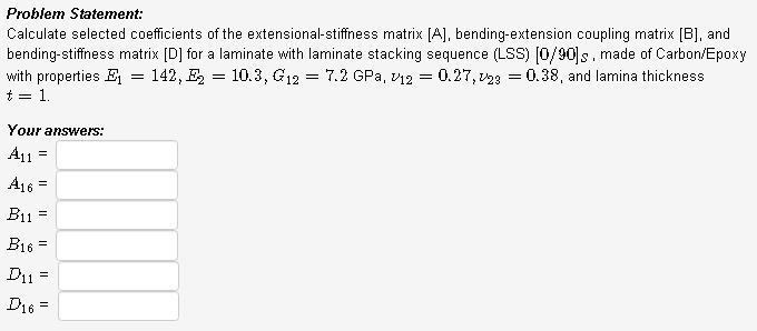
Laminate bending stiffness matrix. Where is the distance from the mid plane of the laminate figure 3. Entries of inverse of laminate stiffness matrix relating to membrane behavior. 0 1185e 12 0 1653e 10 0 2942e 04 0 2798d 11 0 0000d 00 0 7354d 03 0 1653e 10 0 1185e 12 0 1389e 06 0 0000d 00 0 2798d 11 0 3473d 05 0 2942e 04 0 1389e 06 0 4800e 10 0 7354d 03 0 3473d 05 0 0000d 00 0 2798e 11 0 0000e 00 0 7354e 03 0 9876d 10 0 1377d 09 0 2451d 03. The resultant forces and moments are functions of the in plane strains and curvatures berthelot 1999.
The constitutive equation describes the stiffness matrix of a laminate plate. The so called coupling stiffness matrix b accounts for coupling between bending and extension which means that normal and shear forces acting at the laminate midplane are causing laminate curvature or that bending and twisting moments are accompanied by midplane strain. It essentially defines the elastic properties of the entire laminate. In materials science a composite laminate is an assembly of layers of fibrous composite materials which can be joined to provide required engineering properties including in plane stiffness bending stiffness strength and coefficient of thermal expansion.
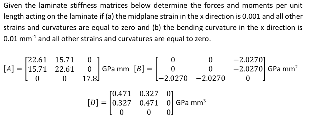
This calculator constructs the a b and d matrices of a laminated fiber reinforced composite please enter the layout information the angle of fibers of each layer of your laminate and click next. These are important to study because they may result in reducing or zeroing out the coupling of forces and bending moments normal and shear. Calculate reduced stiffness matrix q ij for each material used in the laminate if a laminate uses. β ij i j 1 2 6 entries of inverse of laminate stiffness matrix relating to membrane bending coupling.
To assemble the abd matrix follow these steps. Special cases of laminates the symmetry or antisymmetry of a laminate based on angle material and thickness of plies may zero out some elements of the three stiffness matrices a b and d. ε 1 ε 2 γ 12. Normal ε and shear γ strains in ply.
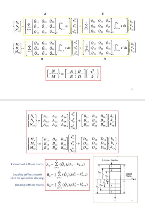
Where n is the in plane force vector m is the in plane moment torque vector a is the in plane stiffness matrix b is the coupling stiffness matrix d is the bending stiffness matrix is the midplane strain vector. Stiffness matrix c the generalised hooke s law relating stresses to strains can be written as the following expression σi cij εj 2 7 where σi are the stress components cij is the stiffness matrix and εj are the strain components. Finding stiffness matrices a b and d step 1 of 5.
Composite Tutorial Classical Laminate Theory Clt
Http Buildsoftsupport Com Wp Content Uploads 2017 10 Stiffnessmatrix Pdf
Calculate Selected Coefficients Of The Extensional Chegg Com

Structural Steel Beams Weight Calculator In 2020 Steel Beams Structural Steel Beams Steel Beam Sizes
Http Ppd Docdb Fnal Gov Cgi Bin Retrievefile Docid 2179 Filename Tuesday 2004 20 20esacomp 1032016 Pdf Version 1
Macromechanics Of A Laminate Ppt Video Online Download

What Is The Design And Construction Difference Between A Transfer Beam And An Ordinary Beam Quora Beams Post Tension Construction
Solved Given The Laminate Stiffness Matrices Below Determ Chegg Com

2 Single Row Led Light Aurora Led Light Bars Curved Led Light Bar Best Led Light Bar

How To Fix A Sagging Roof Ridge Beam In 2020 Roof Beam Beams Wood Beam Ceiling
To Calculate The Abd Laminate Stiffness Matrix In Chegg Com

Pin On Mobility For Supple Leopards

Effect Of Matrix Crack Density And Sub Laminate Scaling On The Download Scientific Diagram

